Point Comfort 23

123
123

|
After much searching for a new boat, it came down to either buying a larger, more complex boat or building the boat that I wanted. Since RiversWest had this nice new shop building, and Russ & Mitch were willing to allow the building of a 23' boat, we got the party started in November of 2022.
The first task was to build the building frame. The plans called for a 2 x 8 ladder frame that was 24' long by 4' wide. Joining the lengths of construction lumber is the primary difficulty in constructing the frame. It's just so hard to keep them dead flat. Then, the inevitable twists in the planks create further issues. Once it is constructed, the whole frame must be faired along its length and side to side to provide a flat, square platform. I had always been intrigued by manufactured I-Joists as a basis for a ladder frame. Lengths do not have to be joined as they are available up to 40' long. These engineered wood products are dead-flat across their length and incredibly strong - that's an advantage when the whole thing is on wheels as required in the RW shop. In the size needed, they represented an additional cost of less than $100 over 2x8 kiln dried construction lumber. I estimate that 2 - 4 days were saved on construction of the frame because of planing the structure fair. 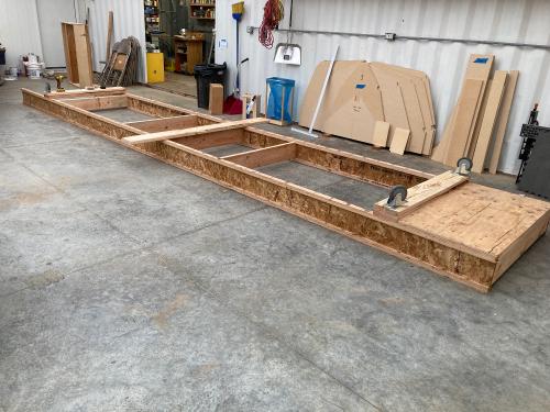 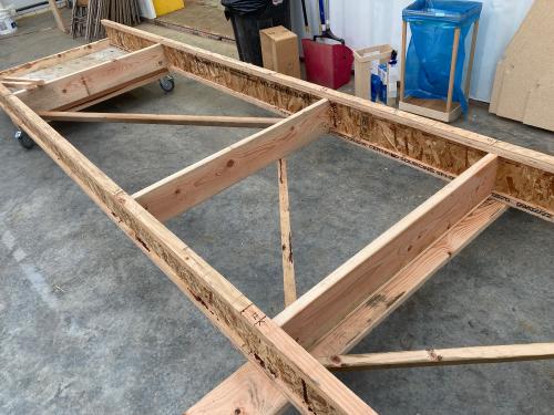 One thing that I didn't foresee is that the I-Joists, while extremely stiff vertically, are 'noodles' laterally, so cross bracing keeps the frame square. Next we'll make the temporary forms and start mounting them. |
|
|
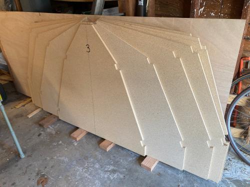
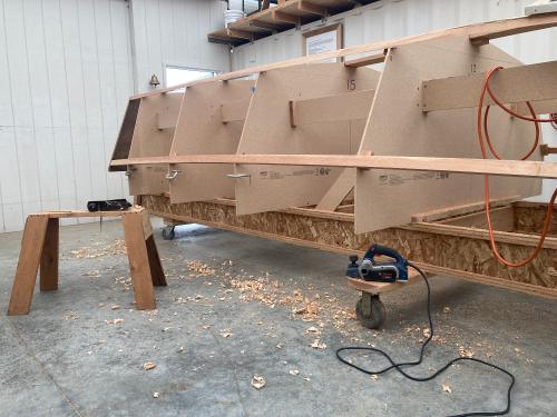
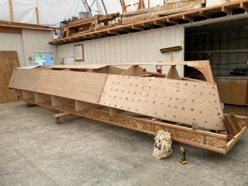
The temporary forms were cut from particle board in my shop at home using the paper templates provided by Doug Hyland and my shop made track saw. All straight cuts, so the track saw was great! Notches for keelson, chine and sheer were patterned and cut with a router. Much cleaner and more consistent than sawing them. All the frames are numbered, have DWL and Centerlines.
 The first form mounted is the center form. It is carefully mounted and leveled with lots of bracing. 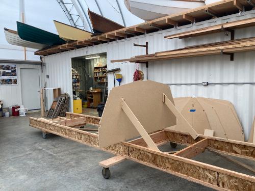 The rest of the frames are mounted at 3' spacing along the ladder frame. All dimensions were checked and double checked, the centerline string was used to locate horizontally, then the laser was used to make sure the centerline of the top of the forms - the keelson notch - and waterlines were dead on. 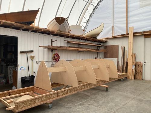 One more frame to mount as of this photo. Later the mount for the transom was constructed and the temporary support for the inner stem is waiting patiently for me to build the inner stem. |
|
|
This post was updated on .
In reply to this post by MarkR
Mark,
Excellent documentation as always. Yeah, yeah. The individual steps often seem so obviously they don't need pictures and comment. But they really do. Keep it up if you can. Also, don't hesitate to give a shout out for help when you need an extra pair of hands. Charlie |
|
|
I will call, Charlie. I really appreciate your help. Right now I'm out of town but will be returning next week, so more progress will be made. In the meantime, I'll bring this up to date.
The next thing to do was to construct the stem and transom. The stem came first. Doug called out four layers of 18 mm plywood for the inner stem. I thought about how many times I'd be sharpening plane irons for the shaping of the stem and thought there should be a better way. I decided on CVG Fir cheeks with a single 18 mm plywood core. All of the planing to shape for the stem will be in the CVG Fir. 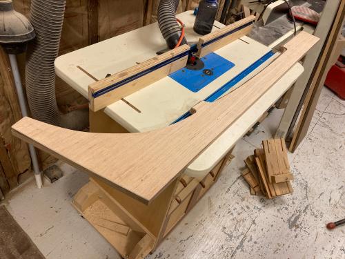 A template was made of door skin material, then transferred to the plywood core. The core was rough cut to shape then finished off on the router table with a pattern bit. 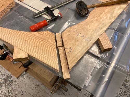 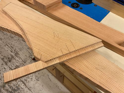 The two sections of the inner stem cheeks were splined to make a strong joint. These will be glued with thickened epoxy. One note: All mating surfaces were painted with epoxy - un-thickened - until they would no longer absorb epoxy. Then the thickened epoxy was painted onto the parts and the parts were clamped up. This avoids starving the joint of epoxy and makes the strongest possible joint. 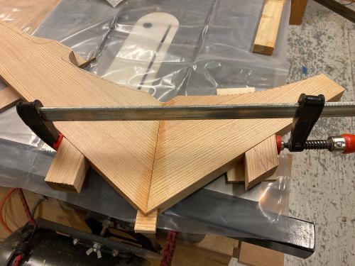 The parts are glued up and clamped. Note the clamping cauls: They were glued to the parts with hot glue. The hot glue holds well but can be removed once the epoxy is set. 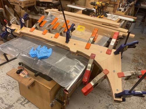 Once the epoxy cured, it was time to glue the cheeks to the core. Same technique was used to glue the cheeks to the core. A combination of screws and clamps hold it in place for the epoxy to cure. 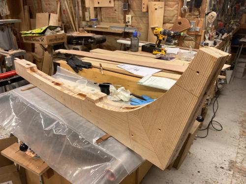 After curing, the part went back to the router table. The plywood core was used for the pattern and it was trimmed to final profile. Bolt holes for the outer stem bolts were drilled and then the bolt holes received multiple coats of epoxy to seal them. |
|
|
This post was updated on .
On to the transom. The biggest issue with cutting out the transom was the weight of the 18 mm Meranti plywood. I was working alone, but our neighbor 'H' came to the rescue and helped me handle the 4' X 8' sheets.
 The plywood was supported by sawhorses, then cut to size using my shop-made track saw. Two pieces were made to provide the desired 1 1/2" thickness. Both of these pieces went into the car to go back to my home shop for gluing. 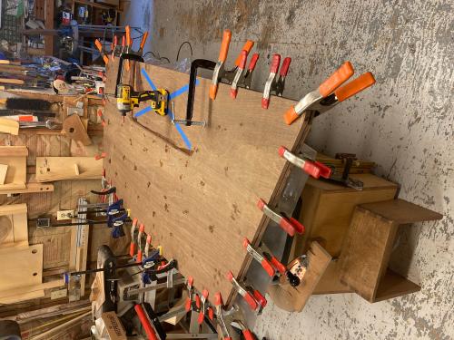 A small departure from the drawings, I notched the inner transom for the chines and keelson. I like the idea of giving it just a little bit more glue area. The transom was glued up using screws to hold the center areas and clamps at the perimeter. On one piece of plywood the motor well cutout was made and finished. The second piece was left blank. Once glued, the second piece was removed with a saber saw and finished off with a pattern bit in a hand held router. Time for it to go back to the shop and onto the building frame! |
|
|
This post was updated on .
The Keelson scarf is the next task. The joint was first roughed out on the bandsaw. The joint is 5 1/2" wide by 14" long in the 1 3/4" thick keelson.
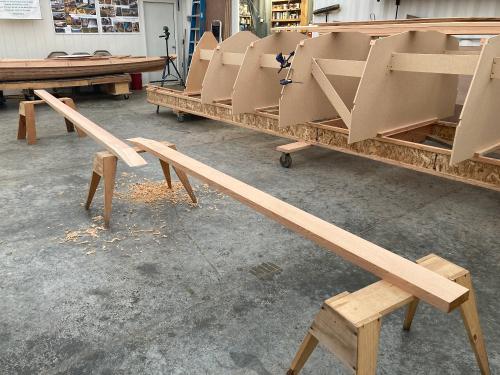 The final mating surfaces were hand planed to fit. The joint was glued up using screws and clamps. This piece is roughly 23' long - made of one 14' and one 10' timber. 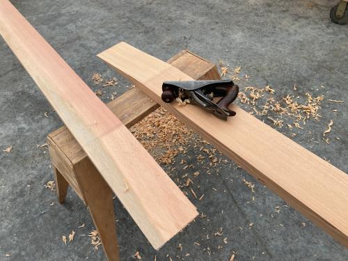 Once the epoxy cured, the top edges were routed with a roundover bit to soften the edges within the boat. It's better to do that now with nothing in the way. One little problem with the glue up is that even though I used WD40 on the screws, the first one that I attempted to remove broke. I'll need to remove that piece of steel or it will come back to haunt the boat. I've got a 'sacrificial' plug cutter to remove the material around that screw using the screw for a guide. For the other 5 screws, I will use a heat gun to heat the screw and release them from the epoxy. |
|
|
Before I left for a short vacation, Russ helped me lift the keelson blank onto the building frame. Then we moved the boat across the shop to allow access to the boats in storage. Upon getting home, I'll need to remove those screws in the keelson and get the stem into place. Once that is done, it will be time to move on to scarfing the chines and sheer clamps.
- Mark |
|
Administrator
|
Love watching your progress Mark, keep up the posts!
|
|
|
This post was updated on .
Thank you, Craig. I will attempt to keep up. Sometimes it seems one has to make a choice between working on the boat or posting progress updates here.
The next piece of work was fitting the keelson in place. First the keelson was cut to the proper angle for the transom, then fitted to the transom notch with a small notch to the upper (lower in the photo) side of the keelson blank. In the first photo it was dry fit with a temporary screw, then disassembled, glued and re-attached with the screw holding it in place. The temporary screw was soaked with WD-40 to assure that I could disassemble it. 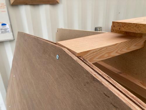 The next photo shows the glued part, with the radiant heater warming the joint, after drilling for the #14 X 3 1/2" bronze screw. This joint will get two more permanent screws once the keelson is beveled. The outer transom plywood piece isn't quite perfect, but it is larger than needed. It will be beveled to take the planking. 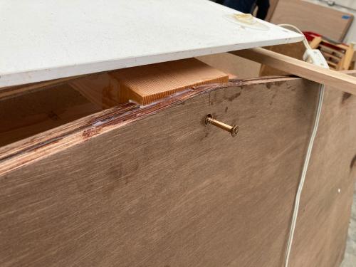 Then we moved forward to the stem. The stem was positioned for correct length from bulkhead 3 and alignment to the building frame. It was a 3 dimensional puzzle. With the help of the laser level to keep the stem vertical and the waterline horizontal, it was locked into its proper place. A temporary screw forward and a clamp held things in place. The hole for the carriage bolt at the aft end of the inner stem was drilled and a temporary carriage bolt had us ready to glue this joint. 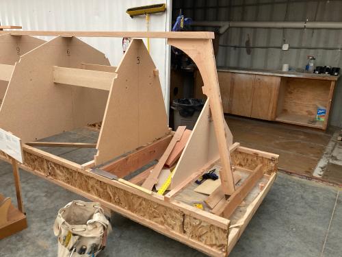 The joint was taken apart, glued with thickened epoxy, temporary fasteners were soaked in WD-40 and it was cinched back into place. The radiant heater was positioned to keep the joint area warm enough for the epoxy to go off. As this was being done, the temp was dropping into the low 40's. 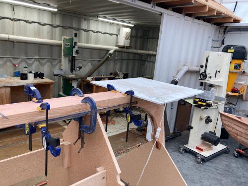 This photo shows the plywood stiffener being glued to the area between the end of the stem and station 4. The heater was placed right on top of the clamps to keep the joint warm. 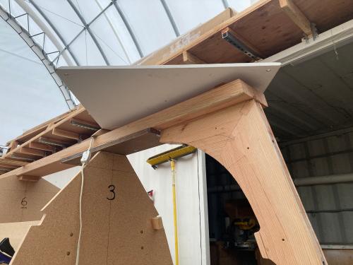 The temporary screw was removed, the hole re-drilled and a permanent bronze screw was driven. While the screw came out easily, the temporary carriage bolt wouldn't budge. For this project I'm using System 3 GelMagic to glue the wooden joints. It's very easy to use and there's no mixing involved - it all happens in the nozzle of the cartridge. What I'm finding is that it's more tenacious in its grip than thickened Silvertip. Sometimes the GelMagic is more powerful than the WD-40 magic! It appears that the undersized bolt (5/16 in a 3/8 bore) allowed a lot of epoxy into the bore. Eventually, to get the bolt out, the parts were heated and the bolt was threaded out with the use of a double nut on the bottom and vise grips on the head of the bolt once it cleared the counterbore. The WD-40 probably helped to lubricate the epoxy 'threads' that were cast into the bore. Now the boat is tied together stem to stern & I'm feeling quite good about it. Next time we will move on to scarfing the sheer clamps and chines. |
|
|
This post was updated on .
Over a period of days the chine log blank and most of the sheer clamp blank were scarfed up. The scarfing jig is set up to be true horizontally and vertically. Lots of clamps hold the two pieces in near perfect alignment.
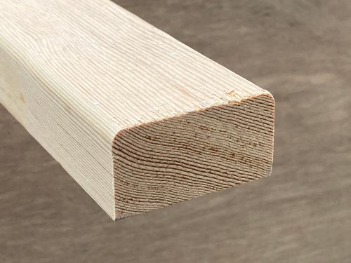
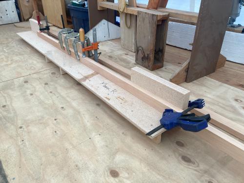 The scarfs were started with a positioning jig on the miter saw. The goal was a well aligned 8:1 scarf. 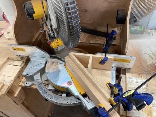 The scarf cuts looked like this: 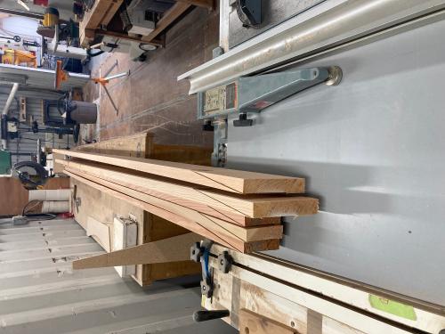 It's a good way to get the bulk of the cut done quickly & accurately. With some modification to the jig, the cuts could be made up to about 3" high, I think. These were well aligned, but couldn't be cut completely through. The result, after trimming with a pull saw looked like this: 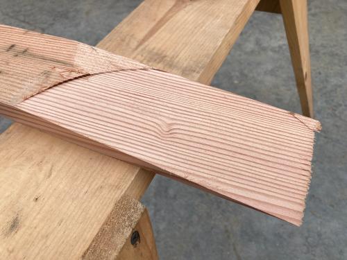 This surface was planed smooth and true, aligned on the scarfing jig, then glued with System 3 GelMagic. The result was one 5/4 X 3 1/2" and one 5/4 X 5 1/2" plank. Each plank was nearly 24' long. The 3 1/2" plank is split at an angle to make the two chine logs and the 5 1/2" plank is cut at 90 degrees 2" wide to make the two sheer clamps. The chine log profile looked like this: 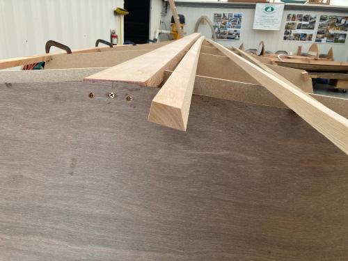 The angle allows the top of the sheer clamp to drain water when the boat is upright. I'd like to thank Russ, Mitch, Bill, Charlie & Mark N. for their help in ripping these pieces. It took two of us and a support stand on the infeed side; then three and sometimes four on the outfeed end to get a well supported rip on the table saw. In the next step, these will be fitted to the building jig. |
|
|
This post was updated on .
Next, the sheer clamps were fitted. The profile fits into the temporary frames well. Small blocks of scrap fir were used to position the pieces.
 The forward ends of the chines were cut to fit on the boat. Once fitted and clamped into position, the screw holes were drilled and then the joints were taken apart, glued with GelMagic and reassembled. 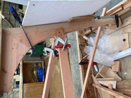 When I get to it, I plan to glue a block between the two sheer clamps. Nothing big, maybe a 5/4 off cut. The sheer clamps went into place well, but there is a lot of tension in those bends. 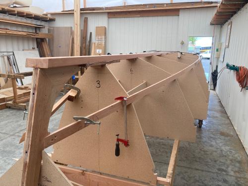
|
|
|
This post was updated on .
Sheer Clamps, Part 1: The sheer clamps were extended by another 2 feet or so then cleaned up and the interior edges were routed for a smooth finish. The pieces are 1"+ X 2" high X about 26' long.
 The aft end of the sheer was sawed on the boat. These were clamped into position and a temporary 3" screw used to hold the aft end in place. It was then clamped to the blocks affixed to the temporary frames. 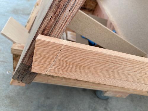 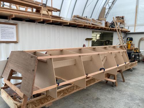 The sheer was fastened at the transom with the temporary screw after gluing. Liberal WD40 was applied to the screw so it would release from the epoxy. The next morning, the temporary screw was removed, and it was re-drilled for the permanent 3 1/2" X 14 bronze screw. 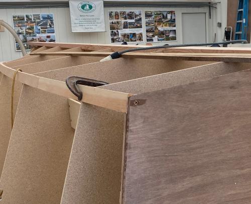 The miter and attachment to the stem will complete this task. |
|
|
I've been gone from the forum for a while - either traveling or working on the boat and not posting. So here we go with an update.
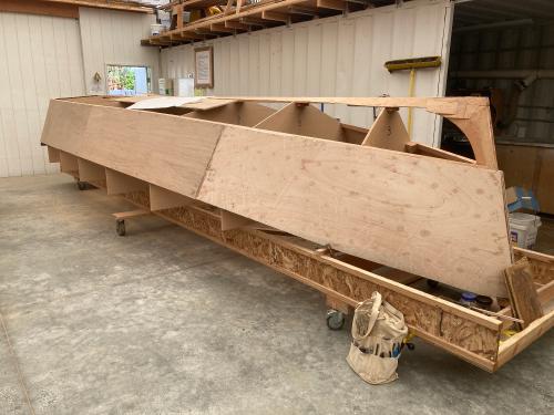
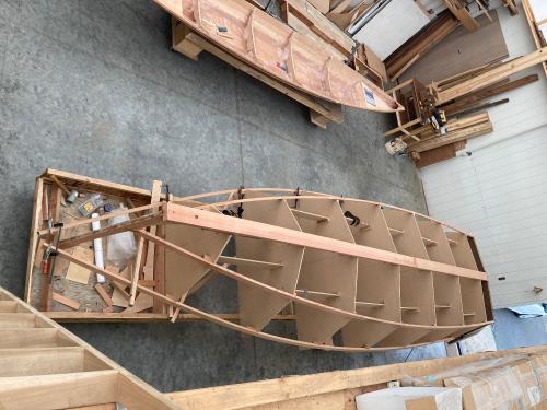 The hull framing. Ready to start removing some material. We will use a couple of power tools to remove most of the materials prior to finish planing by hand. But first, saw cuts were made to give me a guide for how much material to remove. 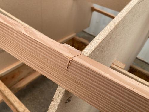 The most aggressive tool I'm using is an angle grinder fitted with an ArborTech carving blade. It is in a shop made frame that self levels between keelson and chine or chine and sheer clamp. After the first day it became known as "The Beast". Sometimes you control it, sometimes it controls you. I'm good for about two hours with this thing, then I'm done! And sore the next day. 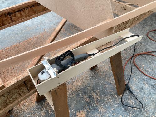 Compared to The Beast, the power plane is downright civilized. It's next in the progression of tools. 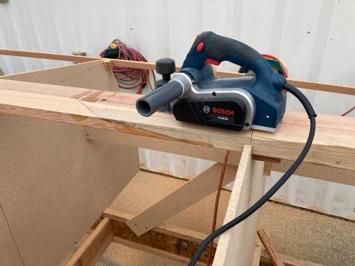 Final finishing will be done with hand planes. The Beast really removes a lot of material very quickly, so you have to watch yourself. In the next couple of photos, the keelson and chine have been roughed out. The forward end of the keelson will be cut with a circular saw/hand saw then finished with planes. 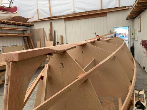 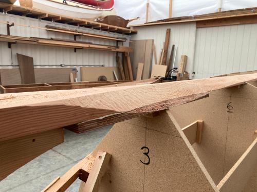 Note the 18 mm plywood piece glued to the keelson up forward. Since the forefoot is so fine, the designer included that to give the planking more support and gluing surface. Here's the pile of chips from about two hours work. I've done this four times so far. 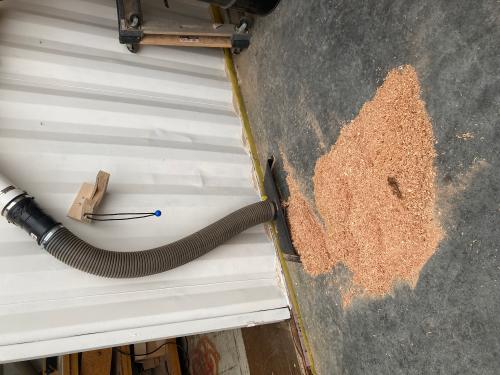 Apologies for the horizontal photos. It seems that the forum doesn't like vertical photos. No matter what I do, they are all horizontal. Next up will be cutting and fairing the forward end of the keelson. Then, some minor fairing of the chine and sheer and we'll be ready for planking. So far, most of this has been done solo. Once I start planking, I'll be recruiting reinforcements! |
|
|
I hate to make mistakes. But it's inevitable, so we have to learn to fix them. "The Beast", the angle grinder in a frame, worked great for the keelson and chine aft. There the angles are mild ones and there wasn't much twist. Near the stem, there is a tremendous amount of twist in the planking and the machine tended to take too big of a bite. I ended up with too much being taken off the keelson in the area around station 3.
The solution was to put some back on. So, 5/32" shop made veneer of CVG Fir was laminated back onto the keelson using GelMagic. The thinner plies allowed the veneers to conform to the concavity of the overcut. 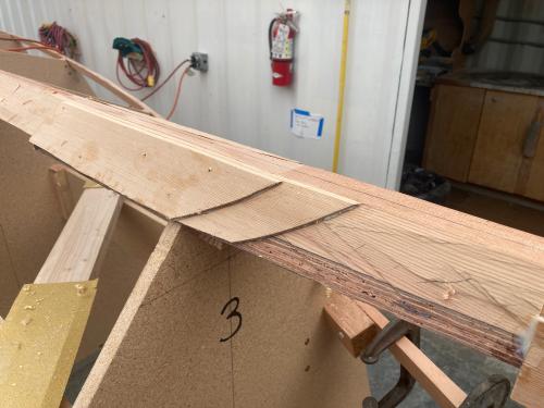 Then the area was shaped with hand tools this time. A drawknife, spokeshave and my trusty #4 were just the ticket! Since the temps were in the 30's at night, a small radiant panel heater was used to cure the epoxy. 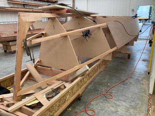 A laminated keelson wasn't planned, but looks like we've got one now. |
|
|
As the forward keelson was being repaired, topside planking was proceeding.
 The chine and sheer were planed and the aft panel was rough fitted prior to gluing. Butt blocks were made and fitted as well. 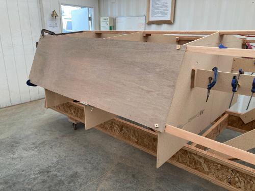 On glue-up day Russ, Charlie, Bill and Mark N. were ready to hang planks. We applied GelMagic straight from the tubes and fitted the panels to the alignment marks. 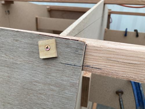 Both aft planks were glued up that day. The hardest part was climbing under the boat to clean up the glue squeeze out. Since all of the cross bracing was still in place, some areas were pretty tight. A couple of days later, together we glued up two more planks. 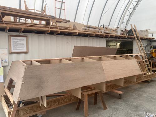 It's starting to look more like a boat. Many thanks to Russ, Charlie, Bill, Mitch and Mark N. |
|
|
Forward topside planking was next thing on the list. All of the landings for the planks were checked for tolerance. Tolerance for gluing is 1/16". Thickened epoxy likes a little 'room' to develop maximum strength, so 1/16" is close enough. The forward sections get two layers of 6mm to equal the 12mm on the aft planks. I tried a piece of 12mm forward and while it would go around and make the twist, it seemed like we would be building a lot of stress into the boat. The 6mm went around really easy. Thanks to Charlie for the assist applying the first layer.
 The second layer was applied with our trusty GelMagic, but this time from a bucket and mixed here in the shop. We were after a quantity to be troweled onto the surface. The early Spring warm snap had us hustling to get it all done before the epoxy went off. 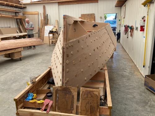 The many drywall screws with plywood washers were pre-drilled on the outer sheet, then applied as clamps to hold the two thin panels together. Once the epoxy cured, the screws were taken out and it's an extremely strong panel. Many thanks to Russ, Charlie and Bill for the help on the second layer. It was nice to have extra hands! 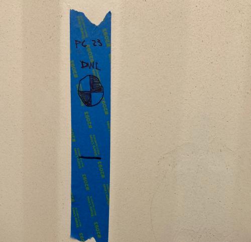 While this was going on, I broke out the laser and marked the walls for the waterline. The DWL was marked, then another line, 3" higher for the bottom paint line. Once the boat is sheathed in fiberglass and primed, we'll use those marks to project the waterline for bottom painting. |
|
|
 The screws were pulled on the bow sections once the epoxy was set. Next thing to do was to make sure the chine sections were beveled properly for the bottom planking lands. The bottom planking butt joins to the topside planking from about station 4 forward. Aft of that, the bottom planking overlaps the topside planking. At the stem, the cut side looks like this: 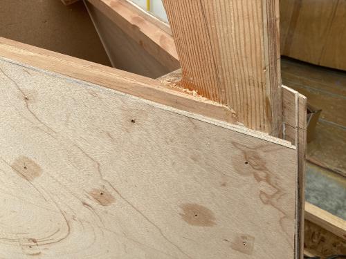 On the starboard side, the plank was set up to be cut. A small circular saw was used set to just shy of the planking thickness. The waste was then cut away with a Japanese Pull Saw. Plastic packing tape was used to define the glue line prior to planking. 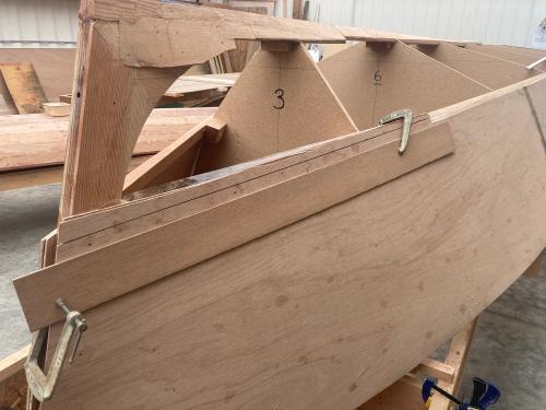 Then the transition was cut using the pull saw, chisel and planes. 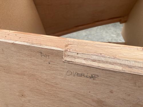 Chine lands were tuned up using a #5. This was to smooth out the little 'waggles' along the chine joint. 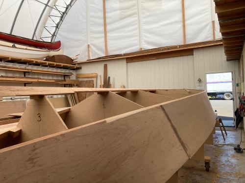 At the time of the photo, the chines were all fine tuned and the keelson was being planed fair with the #5. So far, the cutting tools used have been "The Beast" Frankengrinder, a power plane, #4 & #5 planes, a couple of block planes, spokeshave, draw knife, a slick and a few chisels. One of the chisels is a 2" bench chisel that is wielded just like the slick. But it will fit into smaller places. Next time, we'll move on to bottom planking. |
|
|
In reply to this post by MarkR
It's time for bottom planking. Once again, this will be 12mm as opposed to Doug Hyland's 3/4" spec, but will get a heavily reinforced intermediate stringer and 10 oz glass/epoxy. The two aft planks are roughly 12' long and will need a scarf. So, three sheets were cut to width, then the last sheet was cut in half to make the 12' length.
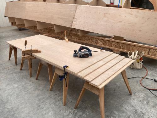 They were all arranged for scarfing and a procession of tools were used. First, the power planer. I'm getting used to this tool - too early to say that I like it, but it's growing on me. It removes a lot of material in a generally controlled manner. Problem is that sometimes I'm not sure if I'm in control. Still learning. 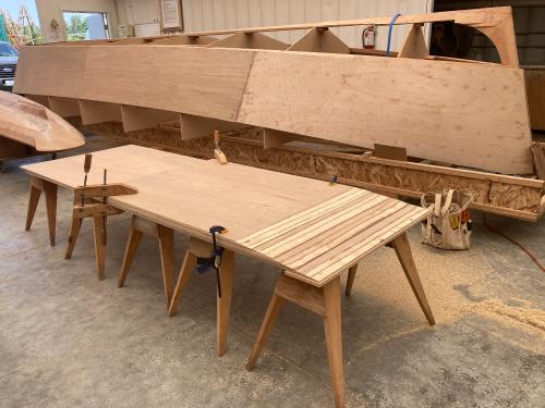 Some roughed out scarfs, not ready for mating. 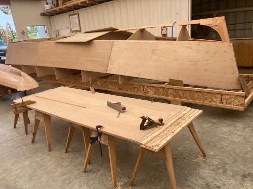 At the point that I was uncomfortable with the Bosch power plane, I switched to hand tools. With the #4 & #5, at least I know when I'm screwing up! The phenolic glue really does a job on the edges of these tools! Lot's of honing. The glue up went as planned. Alignment holes were drilled prior to epoxy. Aligned with pins. Plastic film between the layers. Screws were heavily coated with WD 40. A textbook glue up using Gel Magic. Great product that is saving me a lot of time! 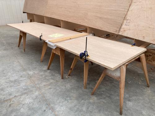 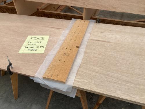 So far so good! I'm happy with the results. |
|
|
This post was updated on .
OK, I screwed up again! The lower sheet of the scarfing stack was misaligned. It was way out of whack with a lot of space where a screw forced the layers apart rather than together. It can happen if the clearance holes for the clamping screws are either too small or mis-aligned. So, the scarf was sawed apart with a pull saw generally along the scarf joint. But not exactly, so about 2" of the joint was lost.
 The good news is that the new scarf is really good. I'm learning the nuance of the Bosch power planer, so more of the work was done there. Only a few swipes with the #5 were needed for a near perfect joint. Now we glue it up with GelMagic for a perfect panel. 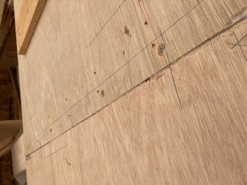 A very good result! 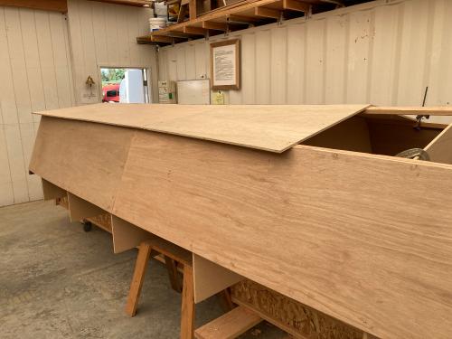 The panels were fitted to the hull. They were marked to within 1/4" for rough cutting to size and temporarily fastened. The centerlines were first cut to angle with the circular saw, then planed to fit with the #5. 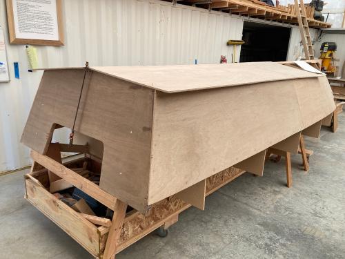 Next, after trimming the panels, they will be fastened and epoxied to the transom, keelson and chines. |
|
|
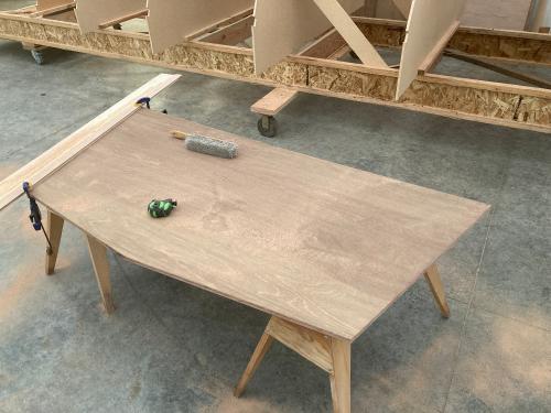
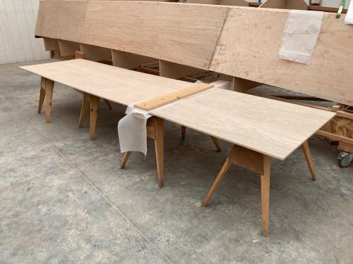
The subsequent re-scarf of the second panel was successful. What a relief! After fitting the panel it seemed a good idea to fair the interior prior to gluing this up. While I was at it, why not mark and cut the panels to fit? So that's exactly what was done!
 Above is before cutting to fit. 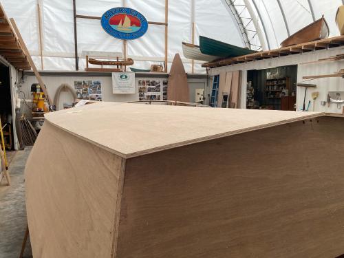 Once they were fitted and cut, our neighbor H graciously agreed to help me relocate the panels so the interiors could be faired. I used QuickFair fairing compound which has been a favorite of mine for quite some time. BTW: I'm using a lot of System 3 stuff on this build. I have no connection with the company other than I really like their products. Oh yeah, I send them my money for really good products. Here's the fairing of the panels: 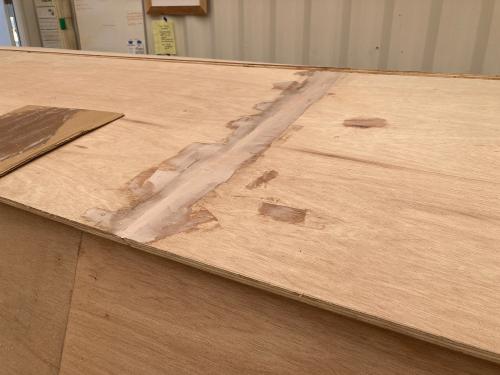 Tomorrow this will get sanded smooth, the panels will be fitted to the hull and registration marks will show where the hull panels land when they are glued. |
«
Return to General discussion
|
1 view|%1 views
| Free forum by Nabble | Edit this page |