Shellback Build Begins
12
12
|
A few months ago I decided to build a Shellback Dinghy. After ordering plans, I laminated the stem and frame, cut out a lot of small parts, scarfed together some mahogany for the gunnels. I basically rough cut everything that was a small part. Then I didn't do much more for a while.
The last couple of days I've been cleaning & organizing the shop. Today I made the cross-town trip to Crosscuts, returning with Hydrotek BS1088 plywood, three sheets of 6mm & one of 12mm. I also bought mahogany for the transom which I plan to finish bright. Looks like I'm really committed to building it now. I'll be setting up to scarf the plywood panels, layout and cut the planking and bottom. The transom needs to be laminated, surfaced and cut. Once that's done, the strong back is fitted with frames, stem and temporary forms. But I'm getting ahead of myself... Better go get after that scarfing. |
|
Mark,
Post photos of crucial steps as they happen. Charlie |
|
I chose to do my scarfs by hand. The plane easily pared the joint. The plywood laminations allowed me to keep track of the 8:1 scarf ratio. The thin panels made for some less than perfect edges. Lucky for me I'm painting this boat! Fairing compound can do wonders!
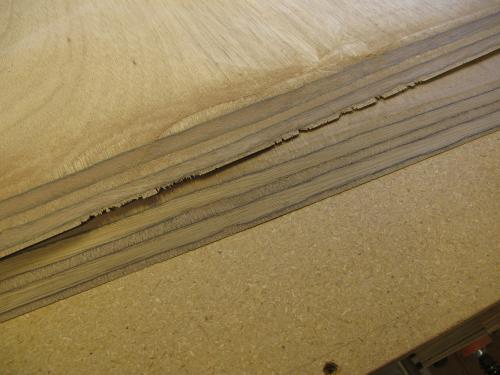 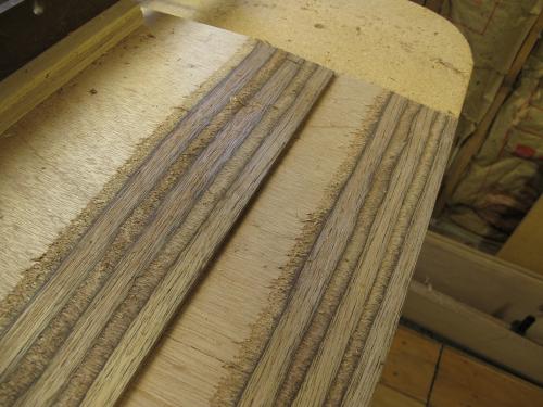 Much to my amazement, the 6mm scarfs were more difficult than the 12mm scarfs as the 6mm panels were more flexible. I learned to mark the 2" scarf length (6mm) then shift the panels to finish off the bottom ones. Otherwise, the upper panel got in the way of a good joint. This is really easy work as the plane does much of it. And with the plane you have a built-in straight edge to keep the work true. 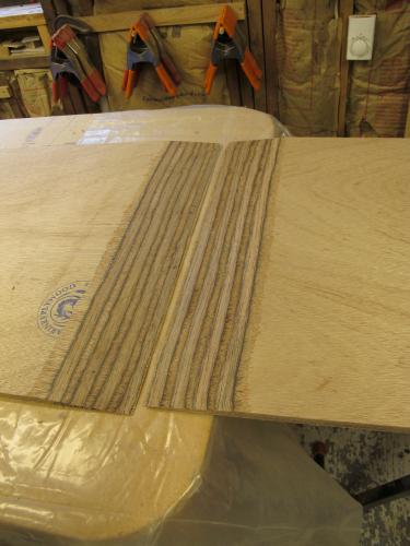
|
|
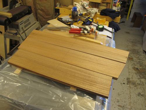
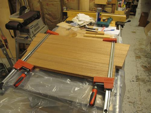
The transom was made of three planks cut from the same board. The glue joint was first primed with straight epoxy then thickened epoxy was used to make the joint.
|
|
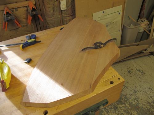
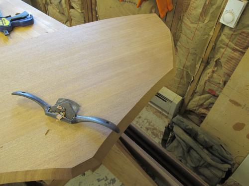
The blank for the transom was sanded and flattened, then the transom laid out. Each surface is cut to a specific angle between 22 and 32 degrees. These cuts were made on the bandsaw, then planed and spokeshaved to exact dimension.
  |
|
This post was updated on .
Today I spent most of the day setting up the strong back and forms. Legs were added to keep it off the floor. It's still quite portable, which is a good thing as shop space is at a premium!
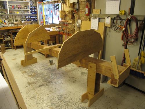 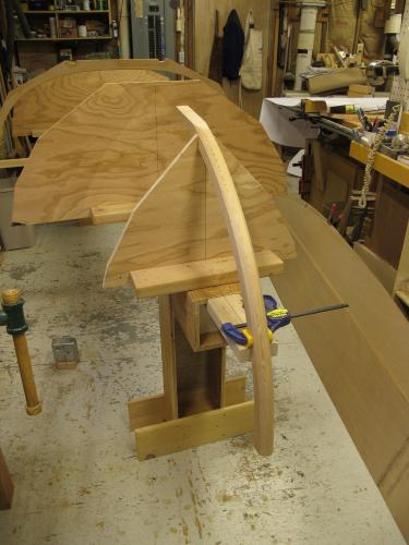 The transom mounting legs were constructed previously. I had to build the stem support today. A note on this detail: If I were to do it again, I would position the mounting block for temporary frame 1/2 to the stern side of the frame, instead of forward as shown here. It will be easier to remove. |
|
Mark,
Your first photo shows two sheets that have been scarfed. The leading edge of the upper sheet is ragged, as you point out. But the leading edge of the lower sheet is as crisp as one could hope for. Did stacking order make a difference? Would using sacrificial pieces on either side of the stack have helped to prevent the chew out the way when planing end grain that sandwiching the piece prevents edge breakout? As you point out, fairing compound hides flaws. But so would joining the now-scarfed pieces, so the crisp edge is exterior on the hull and the less perfect side of the joint is inboard, where it's out of close scrutiny. How thick is your transom stock? 1” inch? That's a hefty piece of timber. Nice, clean building frame. Kudos on that. Charlie |
|
Charlie,
It didn't seem to matter which way they were stacked. The 6mm was much more difficult to work with as the material flexed significantly more than the 12mm stock. I was also joining a 4' wide sheet, so that only made things worse. These are also my first two scarfs. If done again, I think I would have taken a bit more time and rough planed first without cutting all the way to the final fit. Then I'd sand the last little bit to the line and to the final knife edge on the bottom. Do that for each sheet, separately. In the last photo, you can see the 12mm panels came out much better. Not perfect, but better. Transom stock is a little proud of 13/16", cut from 5/4 stock and planed to finished dimension. It looks thicker due to the plank landing bevels. That gives sanding room to finish out at about 3/4" or a little bit more. Mark |
|
Here's the frame and forms with the bottom screwed into place.
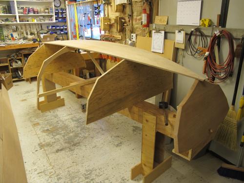 There were some minor alignment issues with the marked centerlines of the frame & forms and the marked centerline of the bottom plank. Once I figured out that the frame and forms could shift ever so slightly on the building frame, it was easy to resolve. I aligned the top of frame and top of forms to be parallel and that issue went away. Everything aligned perfectly. Now, I will remove the bottom plank, glue the stem, frame and transom but not the temporary frames to the bottom, then screw it all together again to cure. Once the glue is cured I'll be able to start planing the landing bevels into the bottom plank. |
|
Mark,
The flexing of the 1/4” ply (that you suspect led to tear-outs on the edge) is the reason I suggested sandwiching the two to be beveled between sacrificial “cheek plates”. If you could cut a crisp edge on stack of 1/2” material, why wasn't it possible to cut a crisp edge on a stack of 1/4”? What was different? Merely the stiffness? Or the fact that one has a nearly unavoidable tendency to “round over” when using a plane over a shorter distance? I'm not sure exactly why one setup worked and one didn't. But that's what I'd test for. Until you told me 13/16”, I'd have guessed 1-1/2” for the transom thickness. You're absolutely right to obsess about getting everything square, plumb, and parallel from the get-go. A floppy structure, like a boat in progress, has a tendency to take on its own, out-of-true shape. I haven't yet built one that taped out exactly symmetrical from side to side. At slow speeds, the lack of trueness doesn't matter. But it's an annoyance I need to eliminate, which means being less casual about my molds. Speaking of which, I keeping admiring the cleanness of your building frame. Maybe something like that is what is needed at the shop for the club builds? Charlie |
|
The issue with the 6mm was both the length and the lack of stiffness. It was backed and therefore supported on the bottom. A plate on top would have eliminated the flex, but would have limited the plane's ability to be used across the panel. (a 3/4" stiffener would have to be placed 6+" away from the panel edge to eliminate interference with planing.) But you may be on to something there - there might be a way.
Ultimately, the tear out occurred at the bottom of the panel where it was supported. It is difficult to plane these relatively brittle, thin veneers across the grain without tear out as illustrated. Rocking of the plane across the joint surface was not an issue. That surface is more than 2" wide in 6mm. The real flaw in this was execution. I did keep getting better the more joints I made. Experience was needed. I think I could make better, if not perfect joints now. To get a sense of the transom and its' apparent thickness, the form ahead of it is 3/4" ply. The frame ahead of that is 7/8". The bevels on the transom are significant. The photo is deceiving. Thank you for the compliment on the building frame. That building frame is a simply constructed box-beam made for the building frame of my canoe. Box beams are marvels of efficient design. As it was originally used for canoe construction, it is a little too small at roughly 6"-7" square. The legs were just scrap ply and pine. It's sturdy, true and relatively lightweight. What's really important to me is that it is portable. If I were to build another for small boats, it would be much wider but still only 6-7-8" deep. The wider frame would give more support to building forms. The issue in building one frame for all boats will be that each frame must be sized in length to the boat being built as the frame needs to be slightly shorter than the length of the boat. This is because the typical small boat bow and transom are higher than the base of the building form or frames for that boat. |
|
This post was updated on .
Mark,
I was thinking that the stiffeners would themselves also be planed. Hence, there would be no thin edge at the bottom of the stack, and I'd use solid stock for the stiffeners, with the grain oriented in the direction the plane travels. If the stiffeners were only 3" to 6" wide, their taper could be cut on a table saw or band saw. But back to your building form. It really is a thing of beauty, and it'd be fun to build some and to make them available to RW's renters, most of whom are making do with saw horses. Charlie |
|
In reply to this post by MarkR
Last night I glued bottom to the stem, frame and transom. Today the bottom was planed for landing the garboard planks.
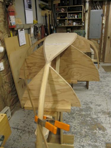 Planing the bottom at the stem required removal of the first screw to avoid nicking the plane iron. 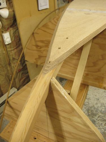 This was about 3 hours of work this afternoon. The garboards will be fitted in the next session. 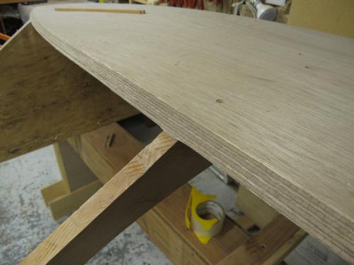 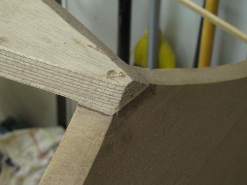
|
|
Mark,
I'm sure the directions say so. But be sure to put the tape on the edge of the temp frames, so glue doesn't drip onto them and make their removal difficult. Also, how much "pre-finishing" are you going to do to the garboard before landing it? Charlie |
|
Yes, Charlie, packing tape is my friend! I was able to glue on both garboard planks, one on Friday and the other on Saturday afternoon. I am fairing the interior of each plank prior to gluing them as it's easier to do that now rather than wait to do it when it's installed and everything else is in the way.
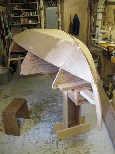 One interesting little bit of business has been pulling the garboard plank into shape at the transom where the hull has a concave shape. This is truly 'tortured' plywood. The designer calls for 1" screws here, but several of my temporary screws have had to be 1 1/2" to get that piece pulled into shape. 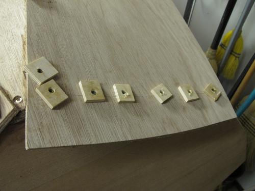 The first garboard took a while to fit. Second one was much easier as I had developed a system. Now it's on to fitting the second plank. Each of these planks goes on and off several times by the time it's rough fitted and glued. The Port second plank is laying on top of the boat at this point, waiting its turn. 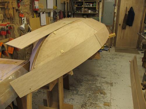 The second plank is landed with temporary screws at the transom. Once this plank is fitted, I will glue it up and trim it. 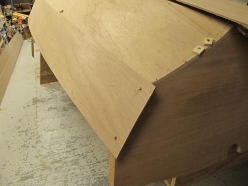
|
|
The second plank was fitted and glued today. It's getting smoother as I go. As with all projects, by the time it's finished I'll know how to do it!
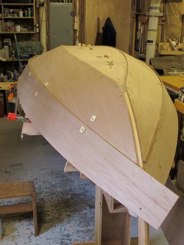 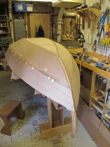 Cutting the second gain was easier than the first. Getting the hang of it. 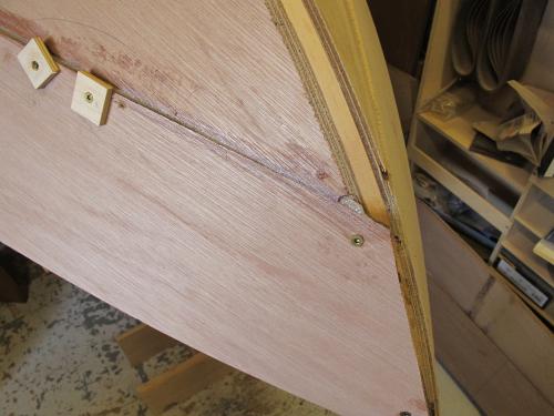 I started to clean up the bottom. Planing the garboard planks flush with the bottom plank is a relatively easy task. Next, I'll sand the bottom flush. The plan is to glass the bottom to give it a little more abrasion resistance for beaching the boat. 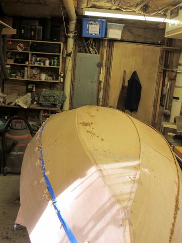
|
|
"The second plank was fitted and glued today. It's getting smoother as I go. As with all projects, by the time it's finished, I'll know how to do it!"
Mark, Ain't that the truth? A saying is apropos: "Build your first boat second." From looking at the pictures, if you stopped now with just two planks hung, you'd have Bolger's Cartopper. I'm finding that better than the brown packing tape for blocking epoxy is the clear stuff. It's thicker, tougher, and holds better, but doesn't leave any more glue residue than the brown stuff. Charlie |
|
This post was updated on .
Charlie,
I hadn't thought of it until you mentioned it, but I am using the clear packing tape. I used it because that's what I had, but it is thicker and tougher as you said. Yesterday the Port side sheer plank was fitted and last night I glued it in place. This morning all of the screws were removed. 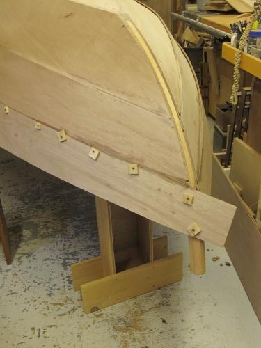 The temporary forms were removed to allow the boat to settle into its shape. Now the only pieces that hold the boat together are part of the final structure: Stem, center frame and transom. 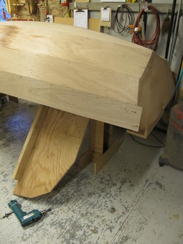 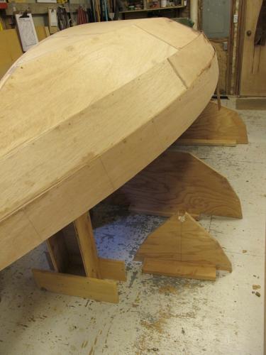 The plank ends were trimmed, all temporary screws were removed and the screw holes drilled for final fasteners. I faired the plank edges and sanded all of the panels. Fairing will begin in earnest over the next few days. 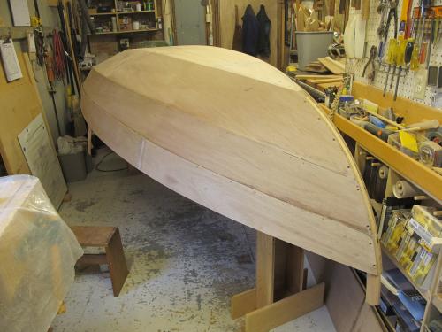
|
|
Mark,
A fairing suggestion. If used with care, a block plane can speed up cleaning up plank overlaps. But do two things: set the blade very shallow and protect either side of the area to be planed with masking tape. If you find yourself nicking the tape, either the blade angle is too aggressive, or it's time to switch over to a sanding block. In either case, you haven't damaged the plywood. Everyone is going to have their own preferred sequence for sanding grits. So, I won't advise numbers. But I find that 100 grit with a firm backing block, followed by 120 on an electric sander, followed by hand-held 150 does a good job of prepping the surface for varnishing, which requires no more prep than for painting. What does matter hugely is the prep work done between coats of paint or varnish. The better that is done, the smoother the next coat lays down. On an 8' hull, the inter-coat prep work takes me 20-30 minutes, or about as long as it takes to lay down the next coat of varnish. The usual safety warnings apply. Wear a dust mask/vapor mask or use forced-air ventilation. Kudos to you for the speed with which you got the hull planked. Very impressive. Also, it should be a huge relief to you. The hard part of the building is now done. What's left is just some finish work that still requires effort and care. But you've now got a boat. Charlie |
|
Charlie,
The plank overlaps were already cleaned up and faired just as you described. One thing that I did was to leave the overlaps a little bit long while producing a fair line. I'll fillet the gap with filleting mix. This will add ounces to the boat while making it a much stronger structure. Final fastening, sanding to 120 and more fairing were the work of today. Out of fifty+ bronze screws I only destroyed three of them, which I count as a victory. Will post more photos when it makes sense. Mark |
«
Return to General discussion
|
1 view|%1 views
| Free forum by Nabble | Edit this page |

